Overview
In 2014, the ECE department borrowed the idea of using a Firefly board as an interactive soldering activity to expose freshmen engineers to the Electrical and Computer Engineering Department at Bucknell. Firefly boards are designed to sync with other nearby Fireflies and blink in a rhythmic pattern, or to simply blink on their own when no other boards are nearby. With the creation of the Maker-E at the beginning of the 2015 school year, the purpose of the Firefly boards was altered to better fit the needs of the department. As with the other Makerspaces on campus, it became necessary to establish a certification process that people could complete in order to safely and correctly operate the equipment within a space. The Firefly boards were adopted to fill this niche for the Maker-E. The creation of a board requires using the majority of the equipment within the Maker-E. As potential makers progress through each step within the PCB process, along the way they will be making their own Firefly board. Once makers complete their PCB, they will place it onto a large magnetic board called the placement board. This board will power the PCBs and provide a template for where makers can place their firefly PCBs.
The placement board consists of two major parts. The first is the board itself: a large magnetic board with copper strips to power the fireflies. The second is power unit for the board, with a small 555 timer circuit that allows users to come up and light up the board for a few minutes at a time.
Process
Magnetic Board
In designing this board, I wanted to make something that would not only be functional and useful, but also aesthetically pleasing. In many ways, we were creating a piece of interactive art. We also wanted to house a large number of Firefly PCBs. We knew that making the PCBs triangular would allow users to make interesting powers on the board, and maximize space.
At first, we designed the board to be 2′ x 3′ with equilateral triangular spots measuring 2.5″ on each side. This gave us approximately 250 spaces for firefly board on the placement board. Later, through the further revisions of the firefly boards though, we needed to increase the size of the PCBs. We also found a need to increase the size of the spacing between the slots on the placement board. The reason for this is the slots were cut from a piece of 1/8″ acrylic in a laser cutter. This acrylic can be very fragile and susceptible to warping on thin cuts. The placement board became very fragile with its current design, so we modified it to have thicker pieces between slots, making the board less susceptible to breaking.
Following these major revisions, we arrived at a final design. The Solidworks rendering of this design can be seen below:
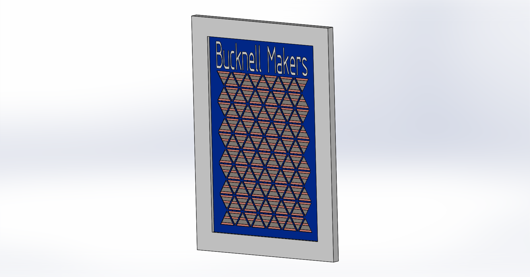
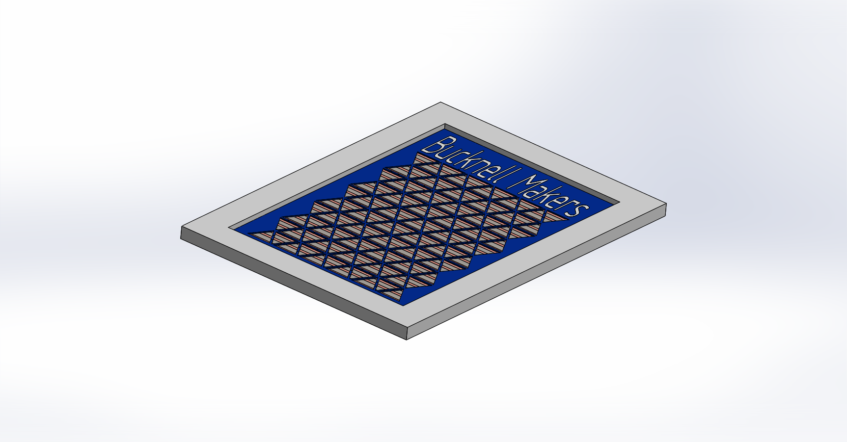
The major components of the board as are follows:
- Plywood Backing: The structure of the board rests on a 3/4″ thick sheet of Oak plywood, measuring 24″ x 36″. All other items are attached somehow to this board.
- Steel Plate: A 30 gauge steel plate provides the magnetic component to the board, allowing the firefly PCBs to attach via their magnet. The steel was only sold in sheets of 24″ x 48″, so I folded the extra steel over the top and bottom of the oak plywood. I then attached the steel plate to the plywood using small, 1/2″ nails. The nails are the same color as the steel, and with the other components on top of the board are practically unnoticeable.
- Copper Tape: Working closely with Laura on the design of the firefly PCB, we decided to connect the PCBs to power and ground in the center of the board and on the corners respectively. We decided that the center of each triangular slot would be the power strip and the top and bottom of the triangles would be the ground connection. Unfortunately, the copper tape repeatedly had problems being insulated from the steel plate, which caused many problems that I will cover later.
- Acrylic Placement Template: Laser cut out of acrylic, then spray painted blue, this placement template provides users with places to put the firefly PCBs that will correctly align the PCBs with the power and ground lines, as well as with the IR receiver and transmitters so the fireflies can correctly communicate.
- Frame: This boarders the placement board, and is purely aesthetic.
The major issue we had with the copper tape was that we were placing it onto a steel plate. Obviously, both copper and steel are conductive, and we needed to keep the individual lines of copper tape isolated, as half were power (9 VDC), and half were ground. At first, we attempted to get copper tape with insulated backing. After the insulating backing proved to be ineffective, we tried using a spray insulation material on the steel. This still proved ineffective, as the copper tape lines were not isolated. Finally, we wrapped the steel plate in clear packing tape, and put the copper tape on top of this. This proved to be a tedious but effective solution to isolate the copper tape lines.
To connect the copper tape lines, we simply ran a strip of copper tape facing downward down the back of the board for both power and ground lines. What allowed us to do this was running the copper tape around to the back side of the board in an offsetting pattern. On one side, the power strips were several inches longer than ground, and on the other side, vice versa. We then connected the overhanging strips to each other with the downward facing copper tape, and soldered those connections to a power cable, which connected to the power box.
Power Box
The firefly boards required a supply capable of delivering a steady 9 VDC at a couple of milliamps of current per board. Luckily, we had a power supply sitting around from the previous firefly board that was capable of delivering this power. To actually turn on the power to the boards though, I wanted something other than a simple mechanical switch.
The user experience I was going for was similar to that of an art gallery. A user may come up to the placement board, turn it on, mess around with the placement of a few of the fireflies, then leave. During this time, the PCBs should remain powered but also not remain on indefinitely, as this wastes power, could burn out the LEDs on the boards prematurely, and also deprives the user of the satisfaction of turning the board on. I therefor devised a design that would allow the user to press a button, and the board would remain on for several minutes. The design of this circuit can be seen below.
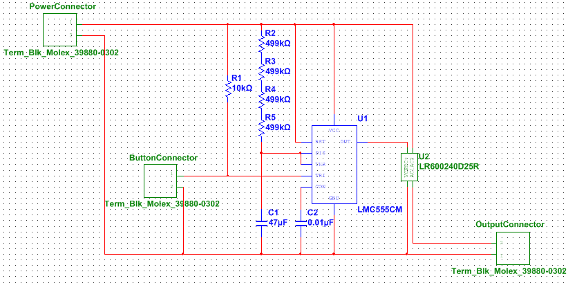
The overall concept is that using a 555 timer in monostable mode, I was able to allow the output to go high for a set period of time, driving a solid state relay which allowed the output to be powered.
I also had to come up with a physical design to the board. The design is meant to be inviting, and will be lit up with LED’s so that the user coming up to the board will have their attention drawn to it immediately. The Solidworks design of this box can be seen below.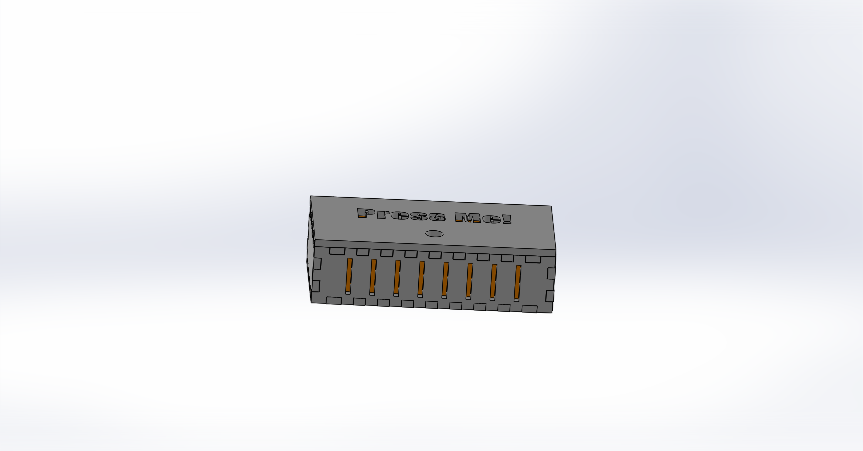
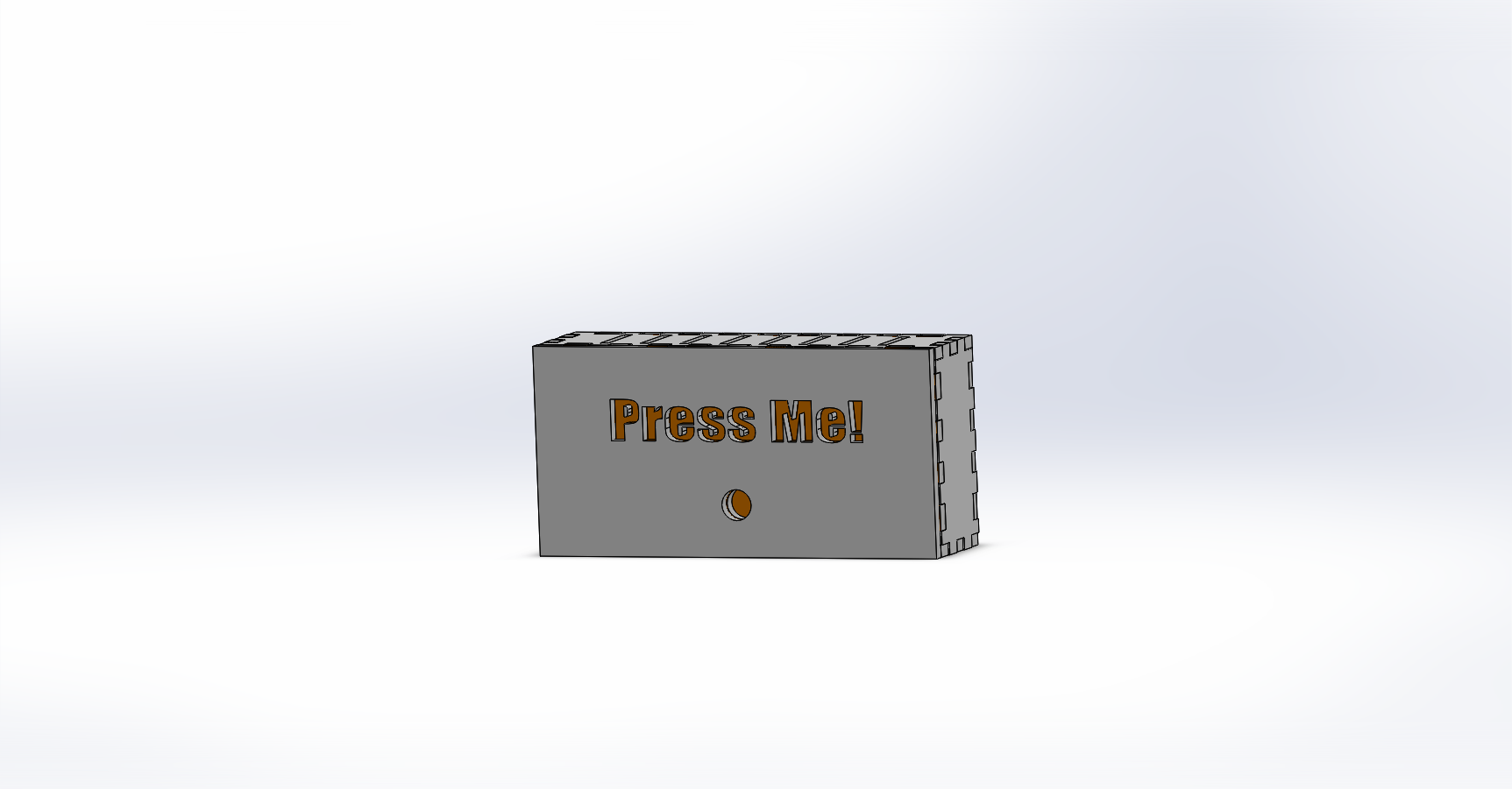
This power box is connected directly to the board and to the wall power. It is capable of powering the placement board off of 120 VAC.
Result
The placement board and power box are both nearly finished. I will be running to Michael’s soon to look at and purchase a frame to house everything. As it stands, the components integrated together all work well, it is just a matter of integrating them with nice fit and finish.
Value Add
This project gives all of those who create fireflies (all those becoming certified in the Maker-E) a place to display their hard work. Moreover, it is a living piece of artwork for the department, providing great PR for those who walk by the Maker-E to the space and those who use it. I hope that in years to come, many people contribute their fireflies, and that one day there will have to be a couple of more placement boards working to display everyone’s work.
Relevant Files
The design files for all parts of the board are linked in the Maker-E drive space in relevant folders:
- Board Design: A SolidWorks model of the main board layout.
- Board Divider: A SolidWorks and STL model of a 3D printable divider that can block the light between fireflies.
- Power Box: A SolidWorks model of the box that houses power components for the placement board.
- Timed Switch: Multisim and Ultiboard files for the switching circuit that allows the board to remain powered for a finite time.